The BranchJoin Nodes
Generating Tangent Matched Curve Joins Using The BranchJoin Nodes
History that led to the development of the BranchJoin node
Demonstrating the BranchJoinNegX![]() Node
Node
There are 6 different types of BranchJoin nodes for 6 different initial
angles of projection. I will show how to use the BranchJoinNegX ![]() to demonstrate the BranchJoin nodes in action. After learning how to use
the negX type it should be pretty straight forward to be able to use the
remaining 5 BranchJoin nodes if you lookat the rest of the BranchJoin examples
encluded in the seamlessWay.zip examples.
to demonstrate the BranchJoin nodes in action. After learning how to use
the negX type it should be pretty straight forward to be able to use the
remaining 5 BranchJoin nodes if you lookat the rest of the BranchJoin examples
encluded in the seamlessWay.zip examples.
To demonstrate the simplest seamless join we will want two Parts ![]() , one Part
, one Part ![]() will be the branching
Part
will be the branching
Part ![]() named l_arm that will
be projected and joined onto the other Part.
named l_arm that will
be projected and joined onto the other Part.![]() named
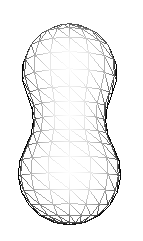
torso. The torso part must be generated by a SurfaceGenerator node
so that we have a surface generated for the BranchJoinNegX node to know
what surface to mould the joining piece to. If u look at the example file
unsawnBranchJoinNegX.smls u will see that the BranchJoinNegX's surface
field references the surface that generates the torso surface. This reference
gives the BranchJoinNegX the information it needs to be able to sense the
surface for moulding the join. In the example file unsawnBranchJoinNegX.smls
a peanut like shape named torso is used to demonstrate a curvy surface
for which the l_arm will be projected onto.
named
torso. The torso part must be generated by a SurfaceGenerator node
so that we have a surface generated for the BranchJoinNegX node to know
what surface to mould the joining piece to. If u look at the example file
unsawnBranchJoinNegX.smls u will see that the BranchJoinNegX's surface
field references the surface that generates the torso surface. This reference
gives the BranchJoinNegX the information it needs to be able to sense the
surface for moulding the join. In the example file unsawnBranchJoinNegX.smls
a peanut like shape named torso is used to demonstrate a curvy surface
for which the l_arm will be projected onto.
The l_arm part is generated using a CCLathe node as well. The joining
part is a cylindrical like shape that has a "pre joining curve" for the
base. For making joins like this the "pre joining curve" must have a curve
that adds up to 1.5708 so that the edges of the base end up with no angle
difference to the projected surface (tangentially matched). We also need
our arm pre oriented to the angle shown below so that it is ready to be
projected in the negative X direction by the BranchJoinNegX node.
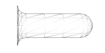
The "pre orientation" of the arm in this example is performed by the
SurfaceTransform
node's orientation field.
The following picture shows the two parts after the arm has been projected onto the torso surface by the BranchJoinNegX node. This set up can be seen in example file unsawnBranchJoinNegX.smls
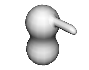
If we play about with the BranchJoinNegX's location and orientation
fields we can see how the l_arm part's vertices are recalculated to make
the vertices mould onto the surface of the torso surface each time we make
a change. (slight changes demonstrate this best)
The BranchJoinNegX's orientation fields can be changed to change the
angles of projection to any angle on the y axis and this node allows for
a wide range of other orientations. However if we want to project more
down than sideways we should use the BranchJoinNegY node or if we want
to project more upwards than sideways to make legs for example we should
use BranchJoinPosY node otherwise strange results may be seen. It is also
worth looking at how we can change the values of any of the CCLathe fields
nodes still. I have called the joining piece an l_arm but it does not have
to be a arm it could be a nose or any other feature we wish to protrude.
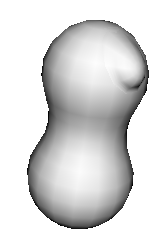
If we change the CCLathe ![]() that generates the l_arm Part
that generates the l_arm Part ![]() so that it generates an inversion of the shape ( at index 1 in the
so that it generates an inversion of the shape ( at index 1 in the![]() change curve from 1.5708 to -1.5708 )
change curve from 1.5708 to -1.5708 )

We can see with a bit of imagination how we can add features like mouths,
this will require some trimming away of unwanted triangles of course which
can be done using build trim nodes such as the DelPoly node. With more
subtle joining shapes we can see how we can add all sorts of protrusions
and indentations to modify the original torso shape.
as shown in example file protrusion.smls
Sawn Joins
The folowing picture shows example file unsawnBranchJoinNegX.smls to the left and example file sawnBranchJoinNegX.smls to the right.
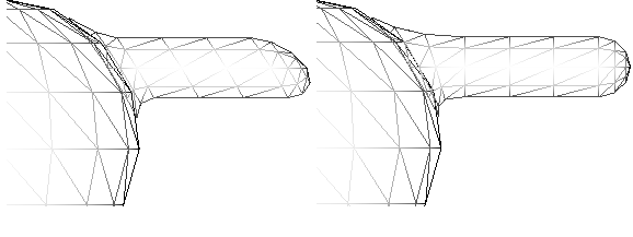
sawnBranchJoinNegX.smls demonstrates how the joining part can join on smoothly to another curvy shape only modifying the first 40 vertices in the joining part. This is possible by checking the sawn field and setting the vertexLen field to a specific number of vertices. Geometry internally generated by the Stem node will have the vertices ordered (the index order of the coords) in a predictable way. This is taken advantage of when using the sawn setting in a BranchJoin node. The joining portion of the joining part is made up of 4 rows of vertices each row equaling 10 vertices which adds up to 40 vertices. Therefor 40 is specified in the vertexLen field for the example SawnBranchJoinNeg.smls. sawn branch joins must have the location more exact than unsawn joines as you will see if you try to recreate this example you will find that unlike the unsawn way the location's x component influences the shape of the join.
The backward field when checked causes the BranchJoin node to start with the last vertex and count backwards in coord index order. This field only has a perpose when the the sawn field is checked and when the value of the backward field is less the the total number of vertices in the joining Part.