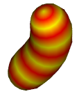
Worm Animation
This tutorial
has been refined to make it easier over the years and must now be one of the easiest
tutorials on the internet that shows how to do skinning, at least if
one stops after operation 5. This tutorial teaches much more than
how to animate worms because it also teaches how to animate snakes, fish, animal tails, in fact
this tutorial encompasses most boned animals including humans that have a central spine
and so the knowledge gained from this tutorial can be applied to the
nurbs_lathe_avatar tutorial to animate the torso, neck and head using
a single mesh.Begin
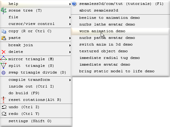
To begin the robot demo move the mouse to the top left corner of the 3d window and select worm animation demo:
All of the titles for the robot demo operations will be shown here in bold beginning with the operation number followed by the title itself.
Operations 0 to 5 should be treated as a complete tutorial that teaches how to make a simple skinned model that can be animated using the same techniques shown in the beeline to animation tutorial.
Operations 6 to 9 are a continuation of the tutorial but are aimed at users who want to learn how to hand edit scripts so if you are more interested in modeling and/or key frame animation skip to operation 10 or to the nurbs patch avatar tutorial after operation 5 in this tutorial.0. Creating a new Seamless file
Click on the new smls file button
![]()
and save the new smls file as worm_animation.smls
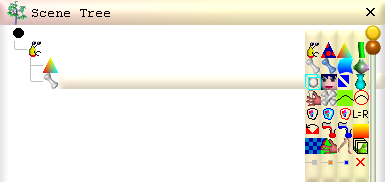
Open the scene tree window
![]()
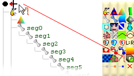
Create a structure of 8 parts and name them as shown
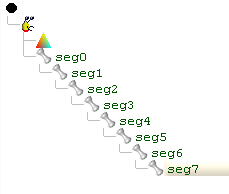
Like this each part  except for seg0 will have a parent part it belongs
to. We will later see how each parent part will have an affect on their descendants when they are animated.
except for seg0 will have a parent part it belongs
to. We will later see how each parent part will have an affect on their descendants when they are animated.
2. Build the Triangles
Select the part named seg0 and click
 so that a NurbsLathe
 referencing seg0 is plugged into the smls
  node.
node.
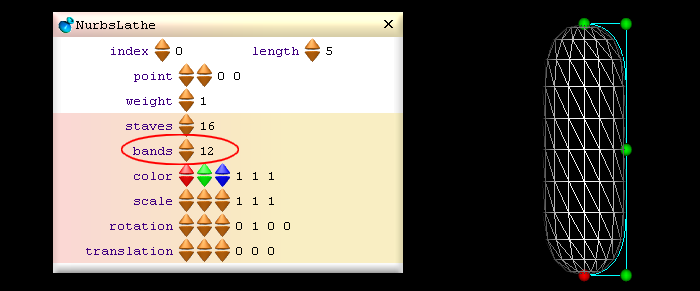
Select the NurbsLathe
and
set the bands field to 12:
3. Transfer ownership to the rest of the parts
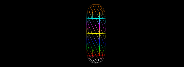
At this stage seg0 contains/owns all the vertices. If we click
 the vertices are coloured to show what parts own which vertices.
To transfer different portions of the vertices to the other parts plug in a TransferOwnership
![]() node:
node:
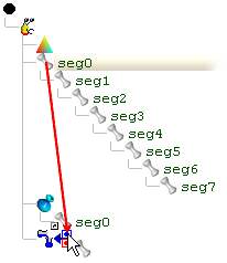
Plug in seg0 as a source reference by dragging the part to the blue dot while holding down the Alt key
(The blue dot won't appear until the mouse is dragged to the right of the
TransferVertex
![]() node):
node):
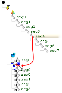
Plug in parts seg0 to seg7 as destination references by dragging each part to the red dot while holding down the Alt key:
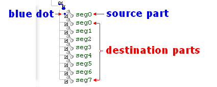
Note after the parts have been referenced, the source part is distinguished from the destination parts by the blue dot:
Click on the TransferOwnership
![]() node to select it and then click on the length up button to add an element for the
numOf and qty fields. Since our rings
contain 16 vertices leave the qty set to 16.
Set the numOf field to 3 so that the seg0 owns 3 rings. Because the first ring is
in fact a single vertex check the beginSP box.
node to select it and then click on the length up button to add an element for the
numOf and qty fields. Since our rings
contain 16 vertices leave the qty set to 16.
Set the numOf field to 3 so that the seg0 owns 3 rings. Because the first ring is
in fact a single vertex check the beginSP box.
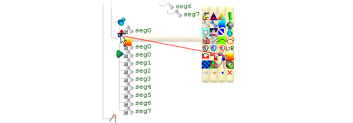
Increment the length again to add the next element for the numOf and qty fields and set the qty value to 1 so that only 1 ring is transferred to seg1.
Notice the
green marker
 in the scene tree shows which destination part corresponds to the selected element.
When in coloured ownership mode the vertices owned by the selected part are coloured
white. When a TransferOwnership node is selected the vertices owned by the marked
part are coloured white.
in the scene tree shows which destination part corresponds to the selected element.
When in coloured ownership mode the vertices owned by the selected part are coloured
white. When a TransferOwnership node is selected the vertices owned by the marked
part are coloured white.
Increment the length button to 7 elements so that there is an element specified
for part seg0 to seg6. We do not need or want an element for seg7 because the last
destination part referenced by the TransferOwnership gets to own the remaining
vertices if no element is specified for it.
To be able to animate our worm we must move each part's pivot point (the point at
which the part rotates around) to the appropriate location. To move a part's pivot
point, select the part and use the
 buttons from the horizontal tool bar or write in the values directly to the part's
pivotPoint field.
buttons from the horizontal tool bar or write in the values directly to the part's
pivotPoint field.
Same as with most other non rotation buttons, they increment and decrement in 1 centimeter amounts and 1 millimeter amounts when the control key is held down.
The yellow dot displayed in the 3d window shows the location of the selected part's pivot point:
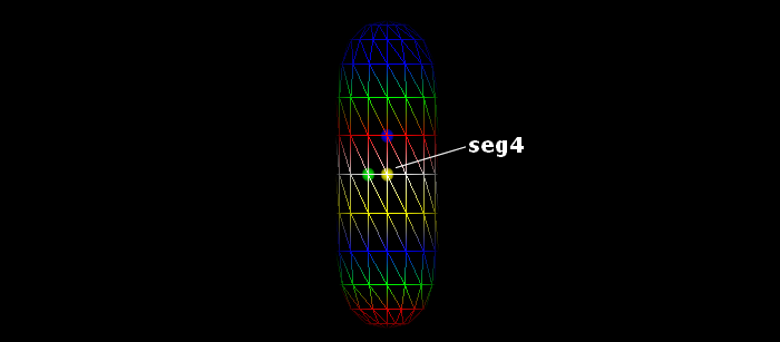
Remember the selected part's vertices will be shown in white.
If you have trouble seeing the pivot point, zoom in using the mouse wheel or use
the zoom
 buttons. To center the view around a pivot point click the
 button.
When moving the pivot points the yellow dot should be viewed from both front on
 and side on

Because pivot points are relative to their parent part, you should move the pivot points beginning from seg0 and ending with seg7. If you need to move a part's pivot point without changing the location of any of the children pivot points, hold down the Alt key while moving the pivot point.
5. Add Anim bar
All we have to do now to animate our worm is plug in an Anim
 node to the Scene
  node:
node:
 node and then drag the anim control points for the selected part as shown in the beeline to animation tutorial.
There is no need for us to hand edit script to animate our worm. If we are not interested in doing this now we can skip to operation 10 that shows how to colour our worm using a ColorSweep.
6. Add calcRot function
The popular way to animate a model is to make a series of poses and play them back interpolated. This technique known as key frame animation is straight forward but if we do not create enough poses our animation may look dull and non life like due to there being no acceleration or deceleration between the key frames. One remedy is to simply add enough key frames so that the movement appears dynamic to the human eye but this can involve a lot more work. Here we will do very little work by using script instead of key frame animation to create precise dynamic movement. This is not necessarily a "better" way to animate but it does have its advantages and if nothing more I hope you will find this interesting.The red rising saw tooth shown in the following image graphs the value passed from an anim bar to it's onFrame (float v) function:
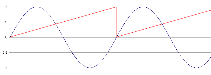
When the anim bar's slider is right at the beginning of the time line, the red saw tooth will be at 0 height which begins a cycle. When the slider reaches the end, the saw tooth will reach 1 completing the cycle. If we multiply the saw tooth with 2 PI radians and then feed this amplified saw tooth into a sine (sin) function the value returned will be a sine wave shown as the curvy dark blue line in the graph.
In this operation we will add the following function:
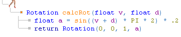
The calcRot function creates a sine wave from the anim bar's saw tooth (float v). The calcRot function multiplies the sine wave with .2 to reduce the range the sine wave swigs up and down. The sine wave is returned as the angle component of the Rotation value. The parameter float d is added to the saw tooth (float v) to add delay (or reverse delay) the sine wave. (create a phase shift)
To add the calcRot function plug a Function
 node into the Anim
node.
node into the Anim
node.Plug 2 CodeLine
 nodes into the Function node
Code the 3 new nodes with:
|
Rotation calcRot(float v, float d) float a = sin((v + d) * PI * 2) * .2 return Rotation(0, 0, 1, a) |
The above lines can be pasted in using Control + V
7. Add anim bar's onFrame function
Plug a MemberFunction node into the Anim
node
node into the Anim
nodePlug 8 CodeLine
nodes into the MemberFunction
nodeCode the 8 CodeLines with:
|
seg0.rotation = calcRot(v, 0) seg1.rotation = calcRot(v, 0) seg2.rotation = calcRot(v, 0) seg3.rotation = calcRot(v, 0) seg4.rotation = calcRot(v, 0) seg5.rotation = calcRot(v, 0) seg6.rotation = calcRot(v, 0) seg7.rotation = calcRot(v, 0) |
8. Add delay
Interesting effects can be attained by delaying each part in time.To do this change the second parameter in the calcRot calls with:
|
seg0.rotation = calcRot(v, 0) seg1.rotation = calcRot(v, .071) seg2.rotation = calcRot(v, .143) seg3.rotation = calcRot(v, .214) seg4.rotation = calcRot(v, .286) seg5.rotation = calcRot(v, .357) seg6.rotation = calcRot(v, .429) seg7.rotation = calcRot(v, .5) |
Because the last delay is .5 the last part will be delayed exactly half way into the sine cycle. This makes our movement look very snake, eel or fish like.
The delay increases by 1/7th of .5 for each part after seg 0.
So if instead we typed in:
|
seg0.rotation = calcRot(v, 0 / 7 * .5) seg1.rotation = calcRot(v, 1 / 7 * .5) seg2.rotation = calcRot(v, 2 / 7 * .5) seg3.rotation = calcRot(v, 3 / 7 * .5) seg4.rotation = calcRot(v, 4 / 7 * .5) seg5.rotation = calcRot(v, 5 / 7 * .5) seg6.rotation = calcRot(v, 6 / 7 * .5) seg7.rotation = calcRot(v, 7 / 7 * .5) |
We would get the same result.
9. Invert the delay
To do this all we have to do is change v + d (add saw tooth with delay) to v - d (subtract saw tooth with delay) in the calcRot function.This makes our movement look much like a cat's tail swaying back and forth.
10. Color the parts
We will use a ColorSweep to colour our worm with yellow and red stripes. We should stop the Anim bar so that we can see where to drag the ColorSweep's control points to. For avatars there can be advantages in colouring parts after the ownership has been transferred to all the parts but for our worm if we insert the ColorSweep before the TransferOwnership, the ColorSweep will only need to reference 1 instead of 8 parts.
To insert the ColorSweep between the NurbsLathe and the TransferOwnership drag the new ColorSeeep to the upper half of the TransferOwnership's icon before letting go:

Click the ColorSweep's length button up to add control points.
By dragging a control point to each ring, each ring will be assured of having the colour we specify. We specify the colour for a control point by clicking it and typing in the colour to the colour field: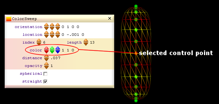
The control points should be dragged with the view front on
Red is 1 0 0
Yellow is 1 1 0
[3d Modelling Software] [Tutorials] [Forum] [Features] [Download] [Gallery] [FAQ] [Worlds] [Avatars] [Links] [Thyme]